Product Code:
Price: Contact
Automation Studio™ E9.0 – Educational Edition helps teachers deliver content, as well as improve the learning experience for students. Use realistic illustrated components to create and simulate circuits. A new Forum is available for quick access to the latest demonstration files and custom libraries. You can also share your projects and experience with other instructors and users worldwide.
Automation Studio™ E9.0 – Educational Edition helps teachers deliver content, as well as improve the learning experience for students. Use realistic illustrated components to create and simulate circuits. A new Forum is available for quick access to the latest demonstration files and custom libraries. You can also share your projects and experience with other instructors and users worldwide.
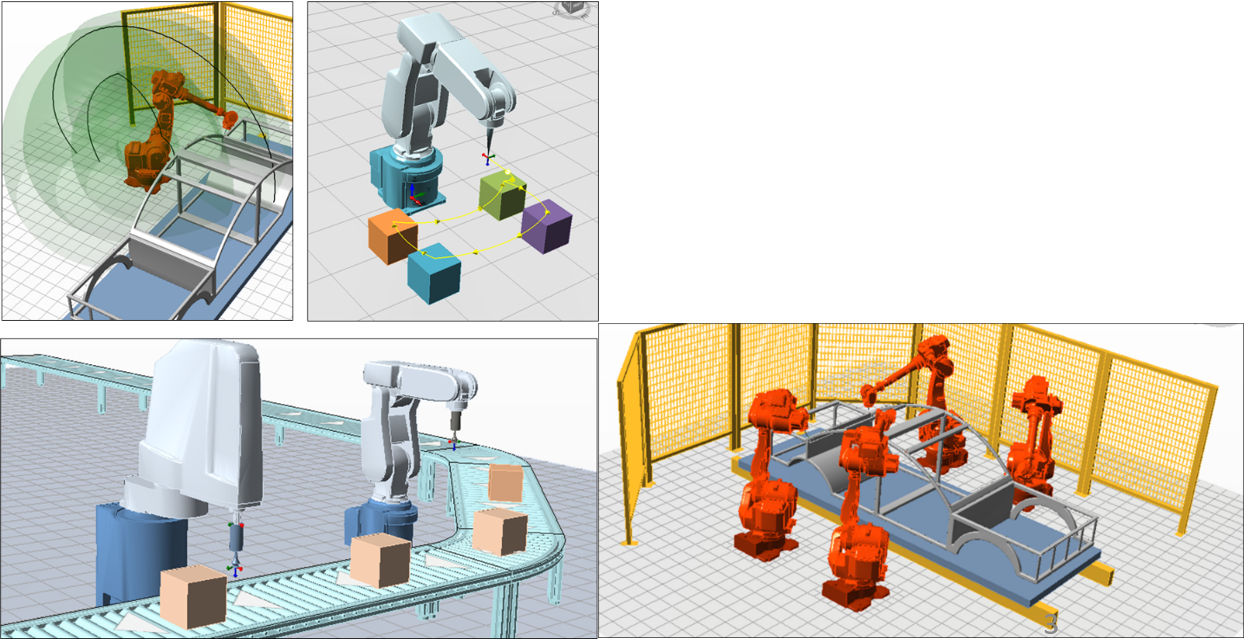
The Robot Workshop in Automation Studio™ provides users with tools to create and simulate complex robotic workcells. It includes robot models that accurately reproduce the dimensions and functionality of real robots, allowing users to work with simulated robots just as they would with physical ones.
The workshop also offers additional robotic objects such as loads and conveyors, enabling users to build their own production lines and test interactions between components before deploying the actual system. In addition, it supports all-in-one synchronized simulations, integrating robots with other technologies within the Automation Studio™ ecosystem (such as PLCs), delivering a comprehensive and immersive simulation experience.
.
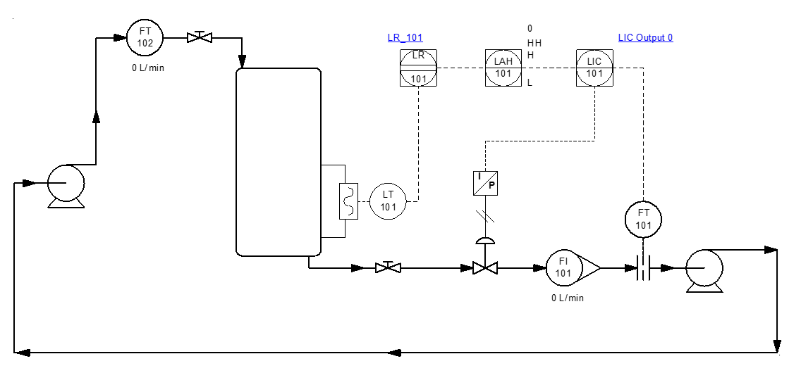
The P&ID simulation workshop provides users with the first version of a process diagram editor.
It includes a library of symbols for the most commonly used components, such as pressure and flow valves, tanks, compressors, pumps, and heat exchangers.
Pipe editing and, more generally, symbol representation follow the graphical conventions recommended by ISA 5.1-2009 and ISO 14617 standards.
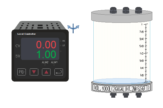
Virtual didactic benches are available for teaching exercises related to level and temperature control.
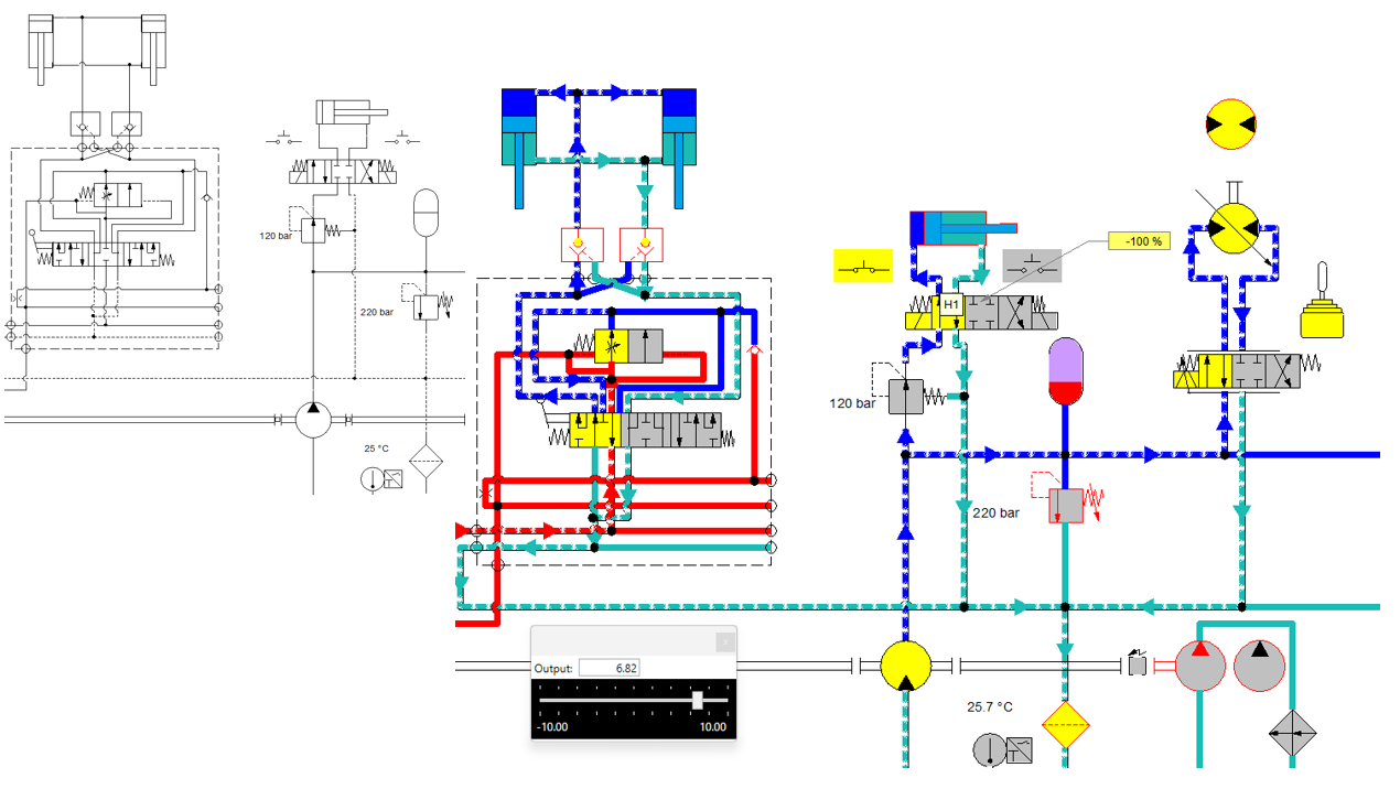
Following improvements made to pipes, cylinders, and directional control valves, it is now possible to modify the visual appearance of all other components during simulation and editing.
Users can visually distinguish between dynamic and static parts, activation states, contained volumes, and pressure zones. Predefined standards are available, and users can also create their own custom standards.
These visual enhancements allow a design schematic to be transformed into training documentation or technical publications simply by changing the document standard.
The development of custom components enables the modeling of multi-technology components. In other words, a created component can handle multiple technologies simultaneously.
For example, an electro-hydraulic component can be created and used within the multi-technology schematic editor.
In process applications, components can be configured with multiple fluid inputs and outputs, such as for modeling a distillation unit.
This development opens up new modeling possibilities, particularly for the electrification of mechanical systems or in process industries where it is not feasible to create every possible predefined model.

A new range of actuators is now available in the pneumatic workshop: pneumatic grippers. These actuators are commonly used in pick-and-place applications.
The new range includes single-acting and double-acting grippers, with angular or parallel finger motion.
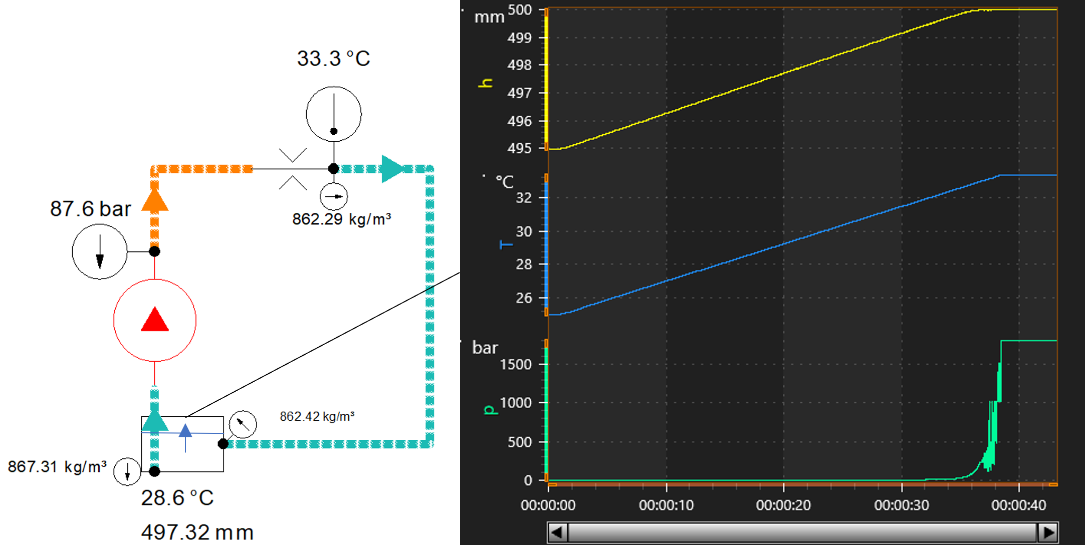
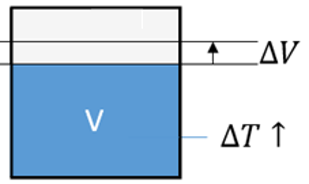
Oil volume variation based on applied pressure has been taken into account. With this new development, the effect of temperature on oil volume is also considered.
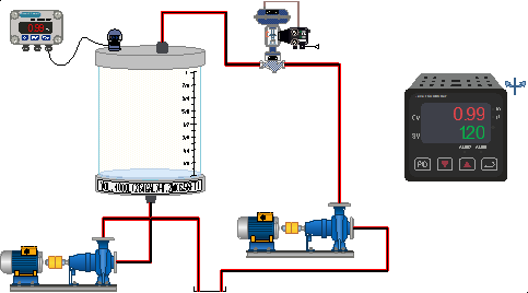
A new library of illustrated components is available to expand the application range of didactic benches. Process components have been added for use in volume control, temperature control, and HVAC-type systems for training purposes.
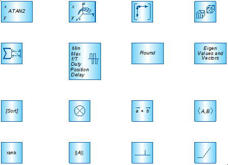
Additional blocks have been added to cover a wider range of modeling scenarios. Some of these blocks also simplify specific functions.
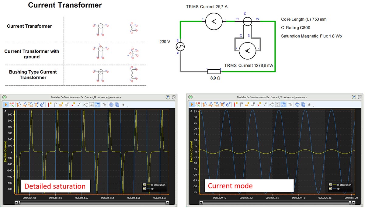
New current transformers feature two simulation models: a simplified model and an advanced model.
The simplified model uses a limited number of parameters, such as frequency, transformation ratio, and maximum allowable values. In addition to simulating the transformation ratio, it also models the safety factor and thermal overload current. If limits are exceeded, an error message is displayed.
The advanced model, which is more realistic, uses structural parameters and simulates remanence and saturation effects.
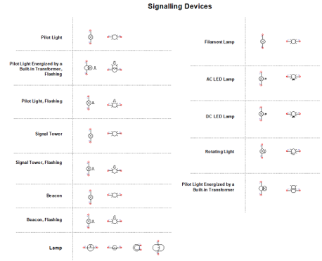
New indicator lights and lamps offer multiple simulation models that allow calculation of voltage, power, luminous flux, and luminous efficiency.
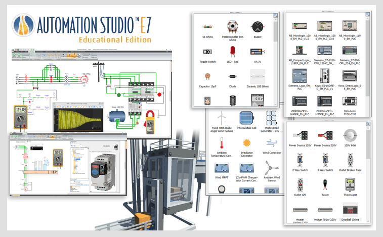
Automation Studio™ – Educational Edition is designed to support teachers in delivering course content while improving the learning experience for students.
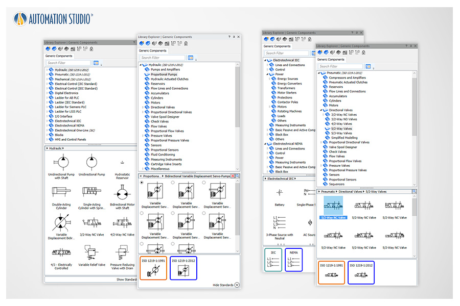
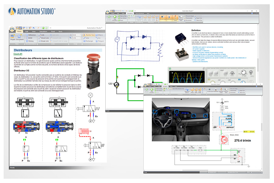
Comprehensive libraries featuring ISO-standard components can be used to teach a wide range of topics related to hydraulics, pneumatics, electrical engineering, and control technologies.
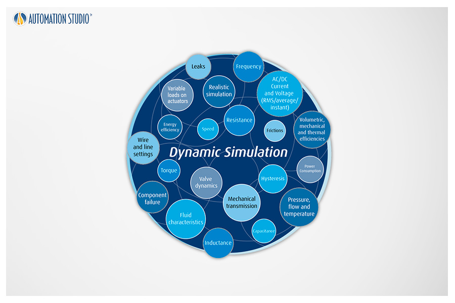
Simulation accurately reproduces system behavior in a dynamic and intuitive way. During simulation, components are animated, and lines and wires are color-coded according to their status.
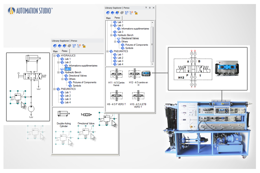
Easily create your own libraries containing only the components required for a specific exercise or laboratory. You can also duplicate any laboratory equipment to simulate it before hands-on practice.
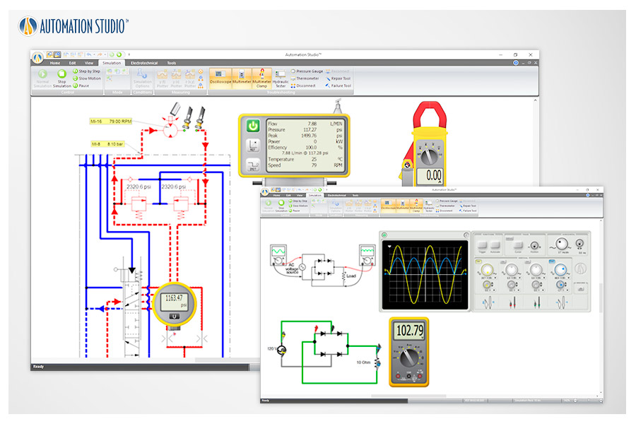
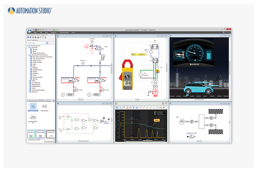
Real-world measurement tools—such as multimeters, oscilloscopes, hydraulic testers, thermometers, and pressure gauges—can be used to recreate authentic measurement experiences.
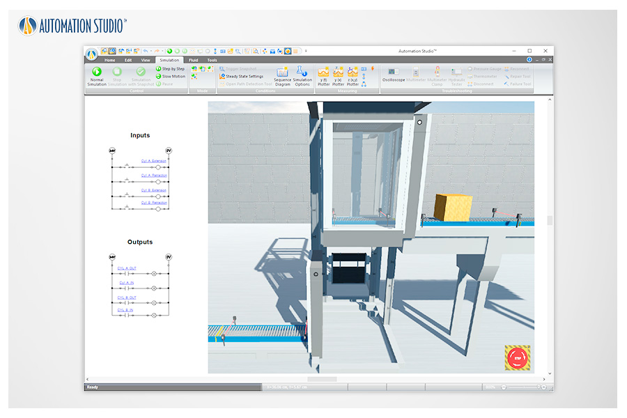
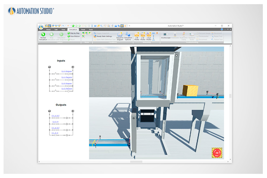
Using the Electrical and PLC Libraries along with the SFC module, students simply link sensors, switches, indicator lights, conveyors, and more to make prebuilt Virtual Systems operate according to the instructor’s instructions.
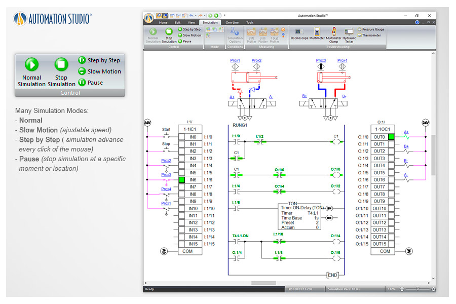
Simulation modes including Normal, Slow Motion, Step-by-Step, and Pause allow users to fully control the simulation process.
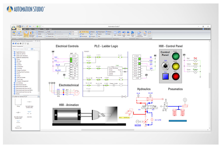
All technologies can be interconnected to create a complete mechatronic system, reinforcing students’ understanding of system interactions.
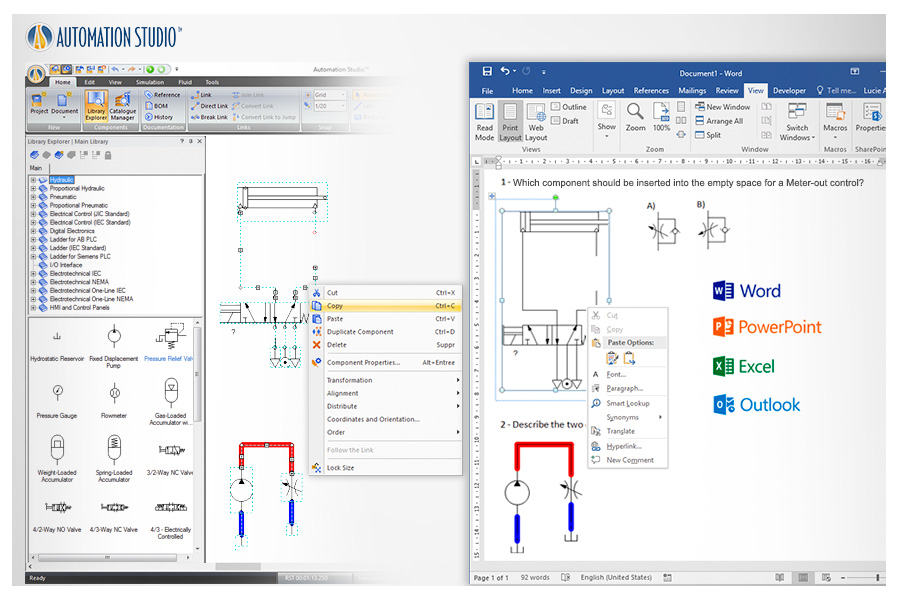
Directly copy and paste into other applications with excellent resolution and color quality to create exercises and teaching materials.
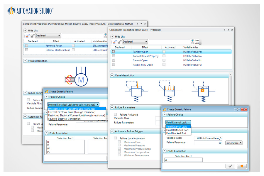
Create or activate predefined component faults to develop troubleshooting skills. Faults can be triggered automatically by predefined conditions or manually during simulation.
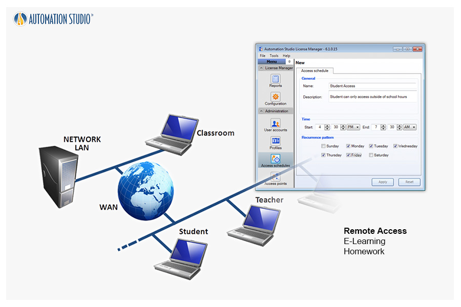
Online remote-access licenses allow teachers and students to prepare and simulate courses and homework from home, school, or the workplace.
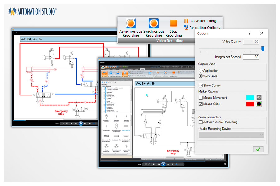
Generate video files of your projects that can be used with other applications or to record full simulations for training purposes.
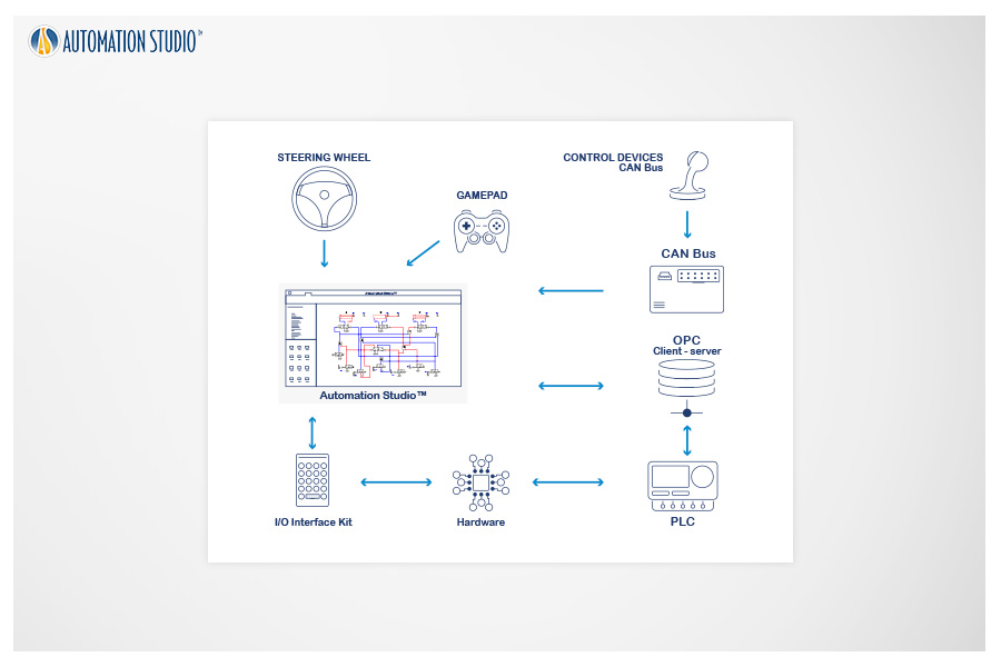
To connect Automation Studio™ with external hardware, I/O interface kits or OPC Client/Server solutions can be used.
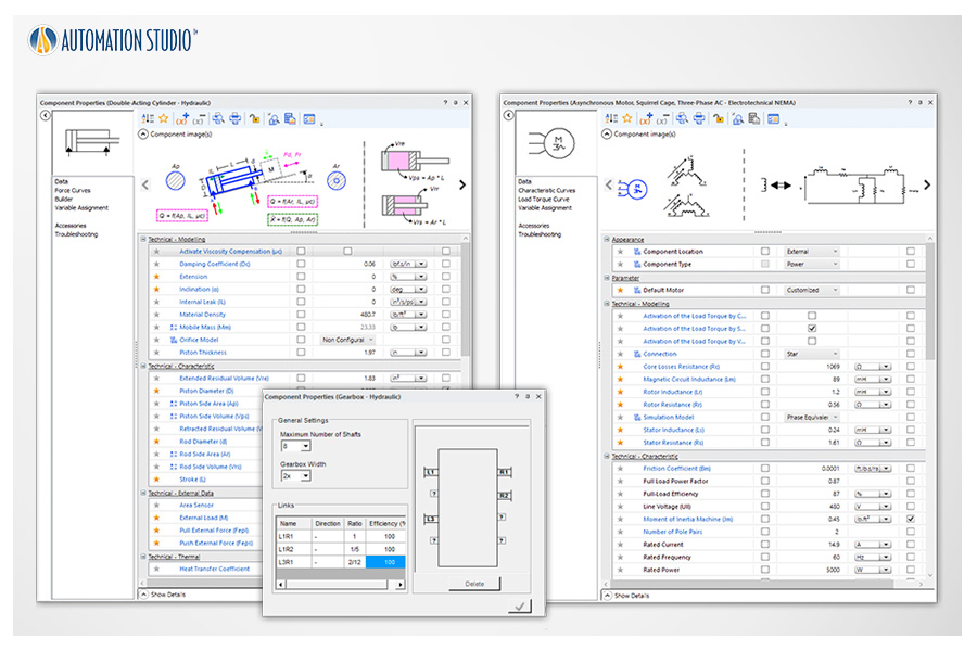
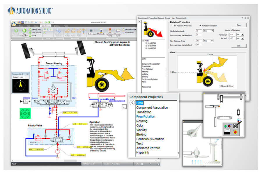
All components include easily adjustable properties to visualize their effects during simulation. Create and configure valves, cylinders, motors, and more to achieve components that are both graphically and technically consistent with real-world performance.
Insert text and images directly into your schematics to create complete, well-documented circuits.
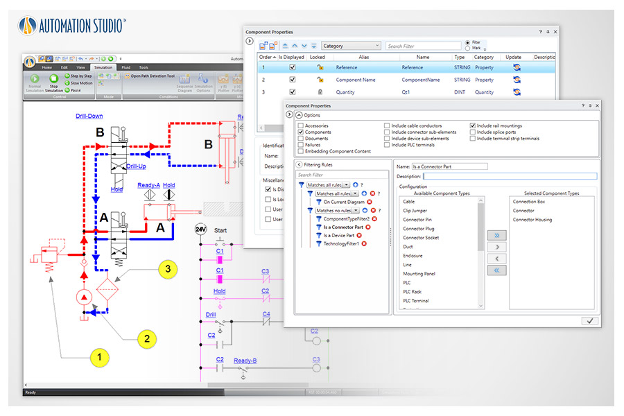
Flexible and customizable Bills of Materials can be defined directly on the schematic or exported to generate reports.
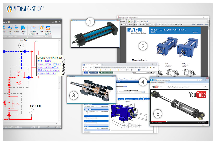
Document your components by adding external links to videos, files, and other resources to enhance understanding of components or systems.
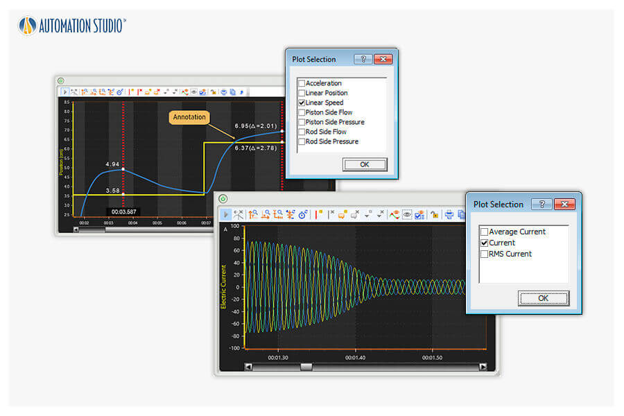
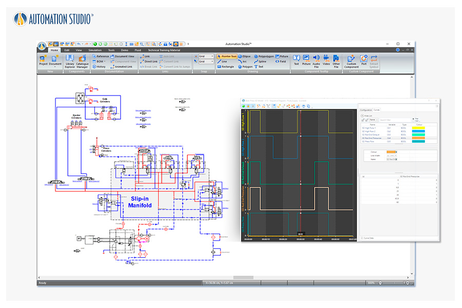
With simple drag-and-drop actions, you can plot simulation parameters that can be exported as text files for further analysis.
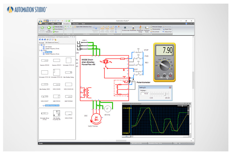
Soft starters and variable frequency drives are available. VFDs are built according to manufacturer specifications such as Siemens™, Allen-Bradley™, WEG™, and others.
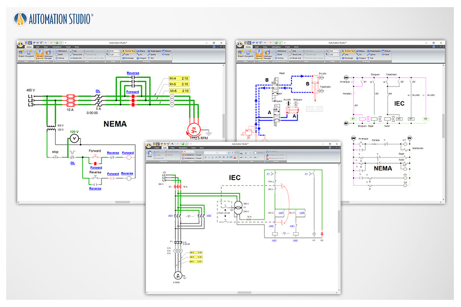
Automation Studio™ supports circuit design using both American and European standards, helping students recognize differences in electrical symbols.
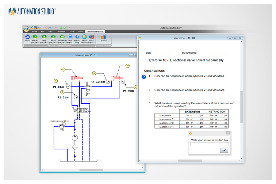
Interactive exercises are available for hydraulics, pneumatics, and electrical engineering. Each includes an automatically simulated schematic with graphical effects to illustrate functional behavior.
Sequence diagrams provide a visual tool for quickly creating operation sequences without requiring a specific control language or electrical control circuits.
With this integration, your projects benefit from the power of the Unity 3D engine, allowing you to see projects evolve in their own environments with a high level of realism. This feature is ideal for adding realism to digital representations developed in Automation Studio™.
All components required for developing automation projects are now grouped into a dedicated library, including electrical engineering components based on SAE standards.
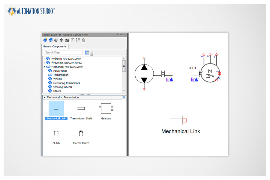
Asynchronous machines, stepper motors, and permanent magnet DC motors are now equipped with mechanical connection ports. Position and speed sensors, as well as shafts and mechanical linkages, can be easily connected—facilitating the implementation of servo systems and integration with other modules.
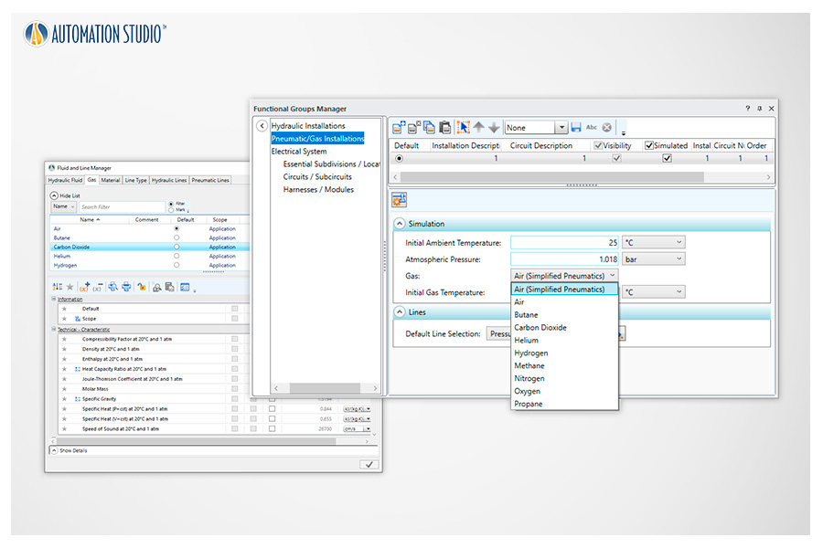
New compressible fluids such as nitrogen, hydrogen, helium, methane, and propane are now available in the Pneumatics Workshop.
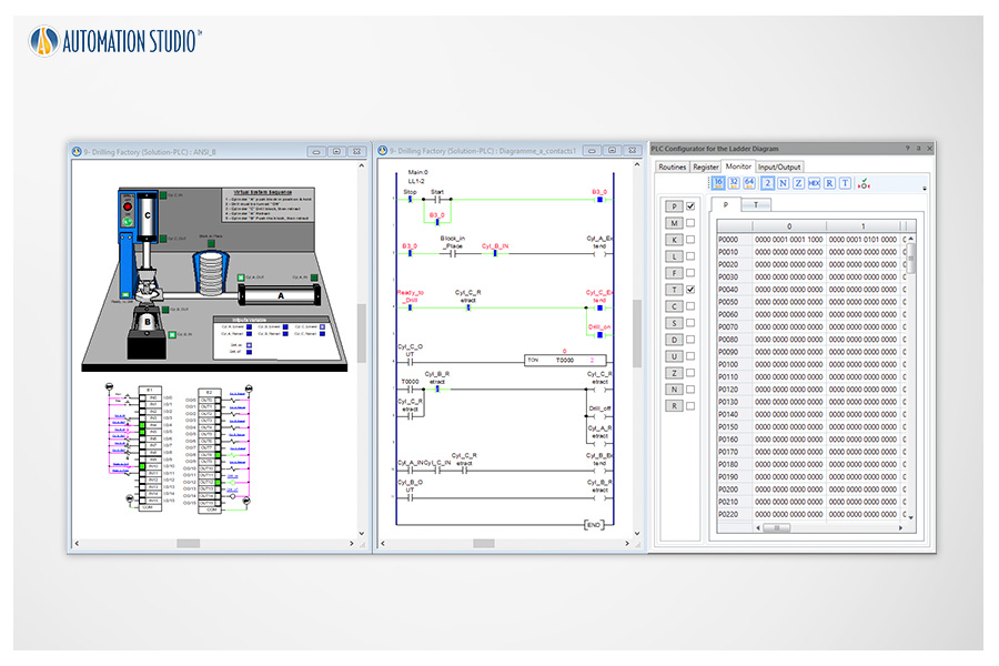
Implementation of a new ladder diagram module based on LSIS PLC specifications.
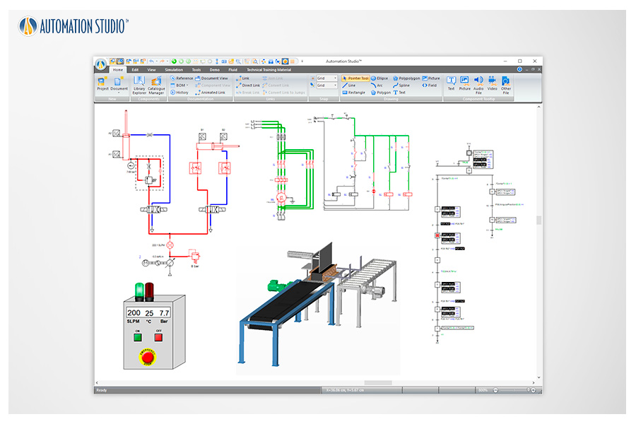
This feature meets training and technical publishing requirements by allowing views from different technologies to be embedded into a single document—for example, a partial hydraulic circuit view, a 3D view, and a PLC view on the same page.
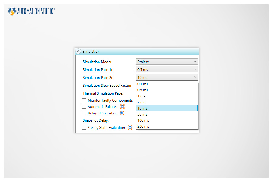
New simulation steps down to 200 milliseconds are available to reduce computational load during simulation, particularly useful for large projects.
Create 2D or 3D effects linked to electrical circuits to enhance schematics and make them more intuitive for students. Use the 3D editor to create or import 3D parts in STEP, STL, and IGES formats.
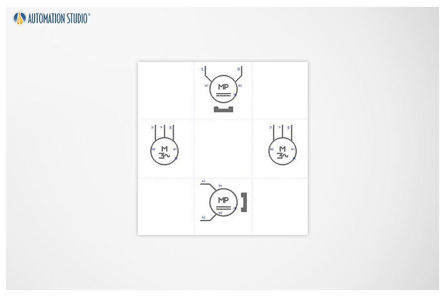
The Electrical Engineering module is now equipped with new induction motors and permanent magnet DC motors.
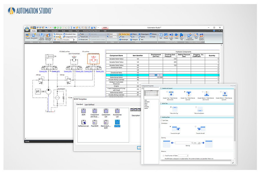
The BOM documentation has been completely redesigned. The new version offers highly flexible customization of displayed information and layout. Component properties can now be edited directly from the BOM.
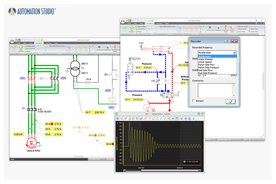
Virtual measurement tools can be placed directly on components to measure a wide range of parameters, which can be recorded and visualized in the Plotter.
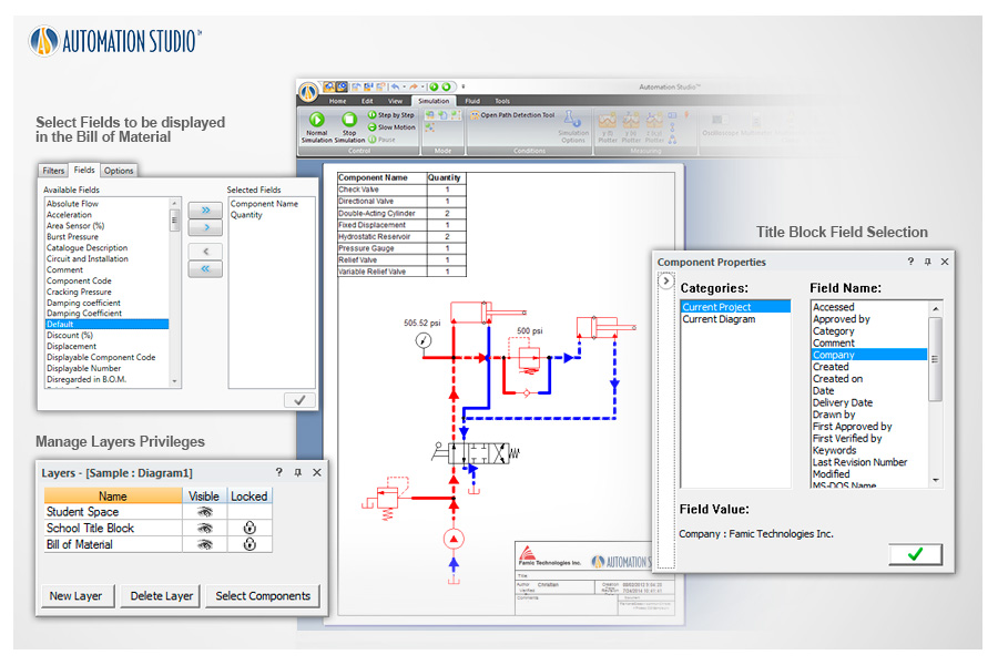
Choose from predefined templates or create your own with default information such as school logos, BOM layouts, and more.
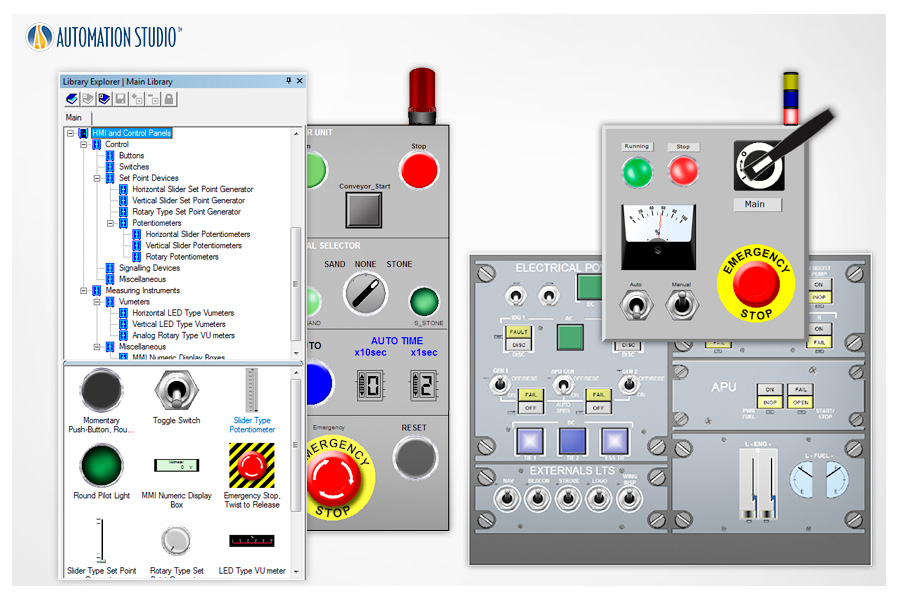
Automation Studio™ makes it easy to create dashboards to control circuits, virtual systems, or equipment.
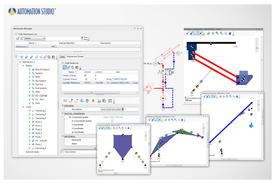
Using the Mechanism Manager, mechanical parts can be linked with fluid power actuators to simulate and animate their behavior.
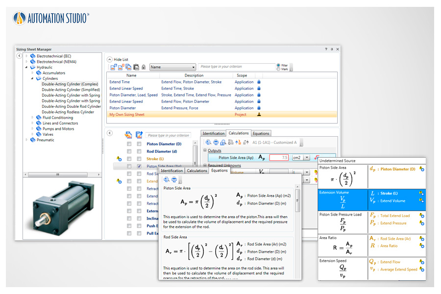
Calculation worksheets are provided for hydraulic, pneumatic, and electrical components, including applied equations and parameter definitions.
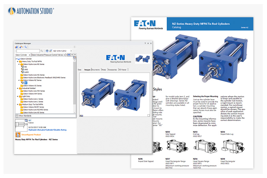
Create and simulate schematics using realistic component behavior from an extensive manufacturer catalog, including PDF specifications and test benches.
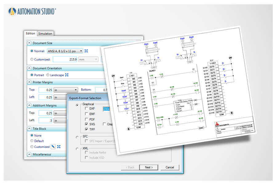
Easily print to any paper size or export your circuits in multiple formats for sharing with other applications.
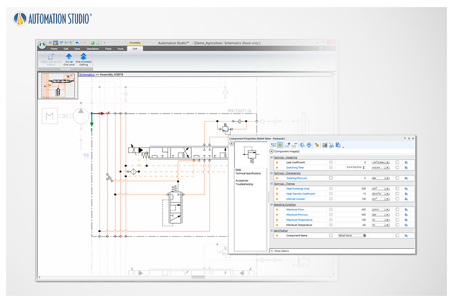
Editing functions (adding, deleting, moving components, modifying component properties, etc.) can be applied within an existing Assembly or Group without needing to ungroup or disassemble components.
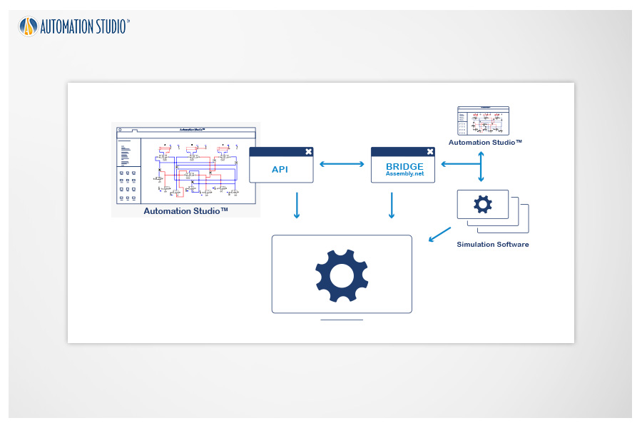
Automation Studio™ can communicate via API with third-party simulation software, allowing users to create Model-in-the-Loop (MIL) environments and co-simulate Automation Studio™ projects with additional multi-physics simulation tools.
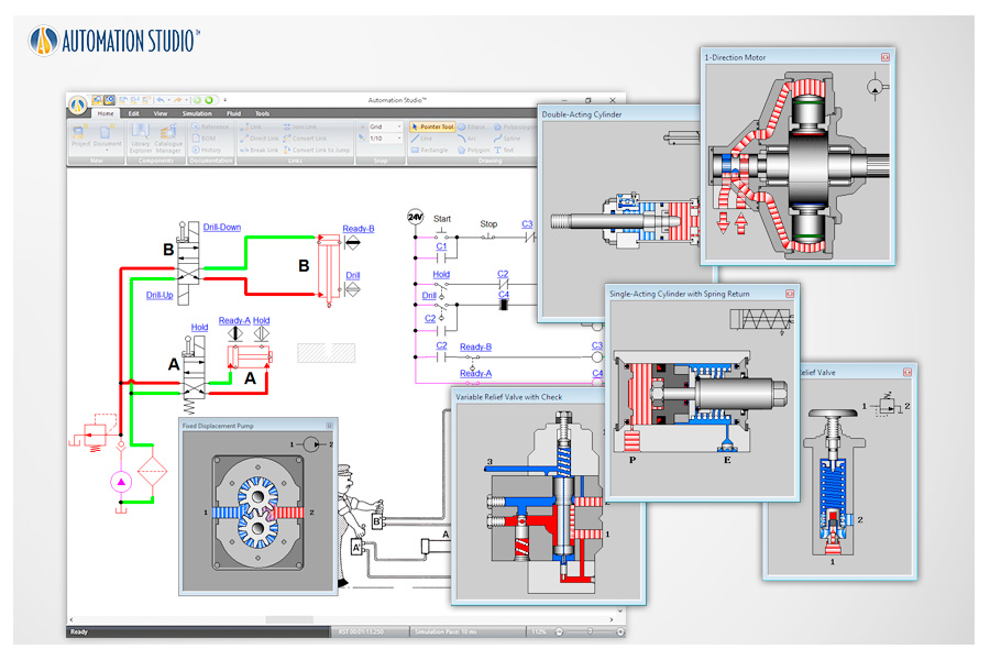
Dynamic component cutaways illustrate internal operation. Animations are synchronized with circuit simulation.

