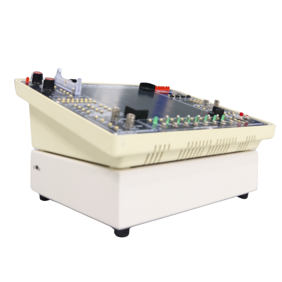
BASIC ELECTRONICS TRAINING MODULE WITH COMPUTER INTERFACE

Product Code: ST.BE.A0018

Price: Contact

  • Device information
  • Specifications
  • Origin: Vietnam
  • Condition: 100% brand new
  • Intended use: For practical experiments in basic electronics; can operate independently or be connected to a computer software interface for data acquisition and control.

Module Characteristics

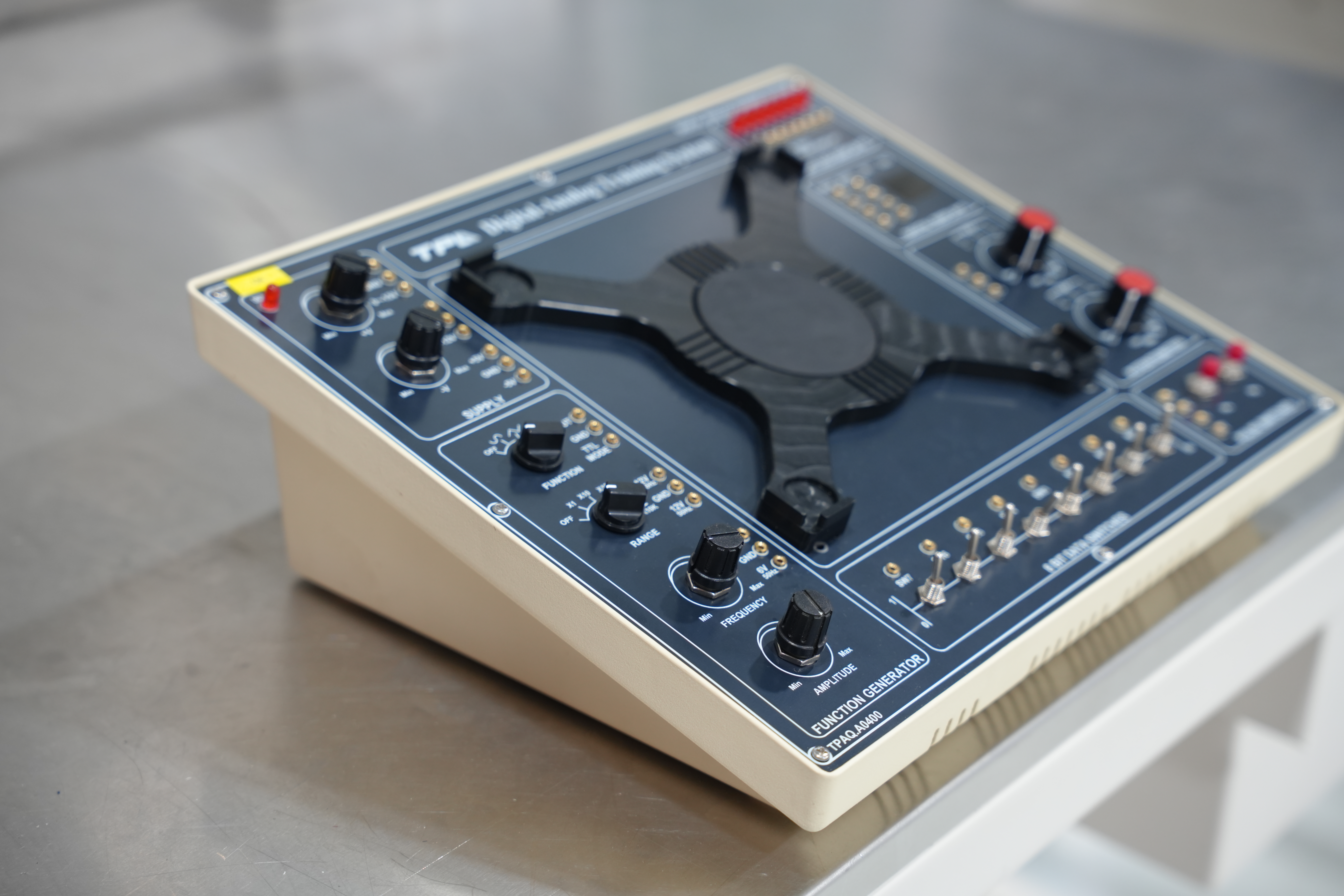
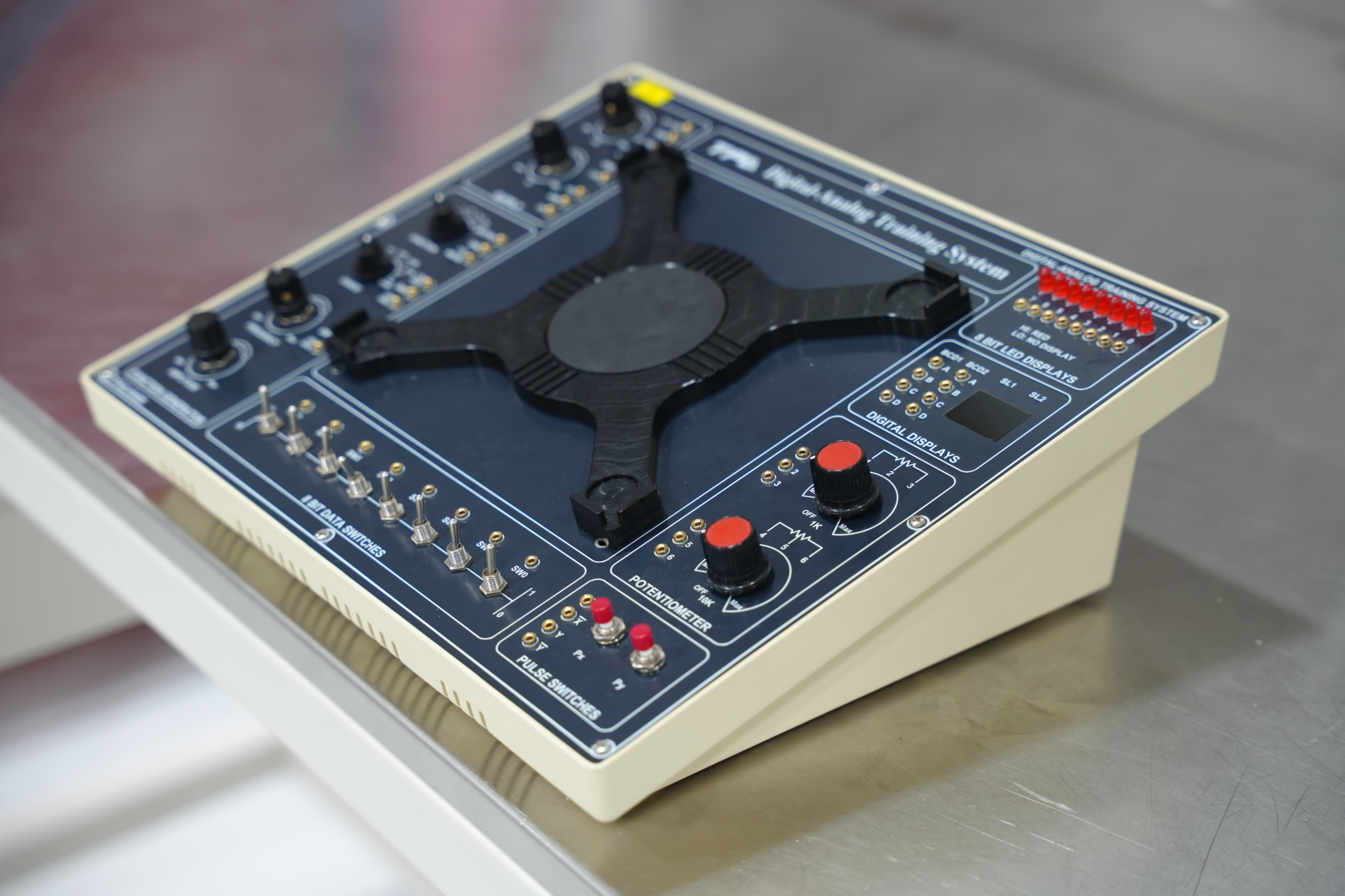
  • The module is designed using a standard plastic enclosure.
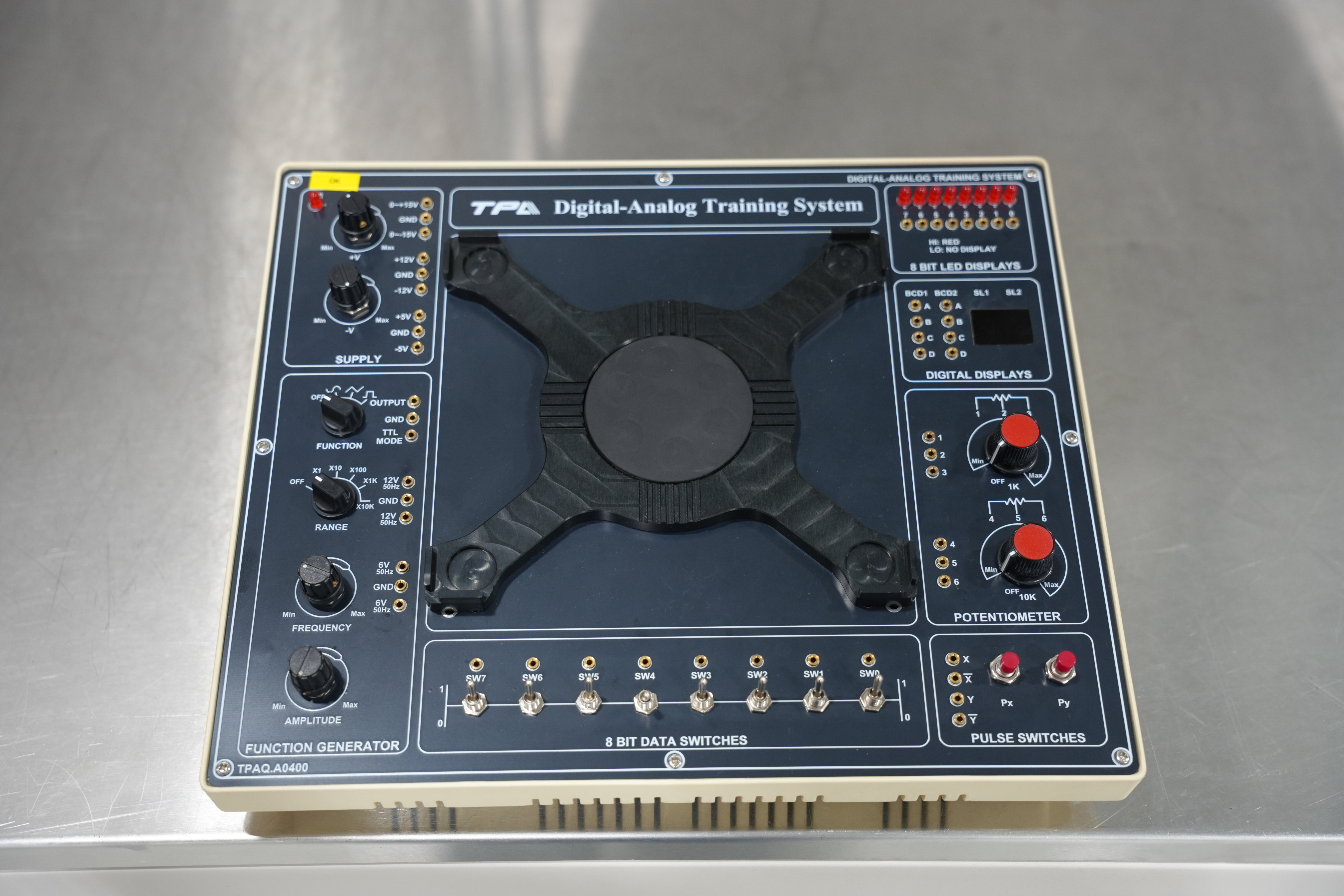
  • Front panel labeling: Film printing on the module surface, ensuring aesthetics and long service life of the equipment.
  • Standard M2 connector terminals.

Equipment and Material List

  • 01 plastic module enclosure
  • 01 module front panel
  • 01 power supply unit
  • 02 potentiometers
  • 08 switches
  • 01 single LED module
  • 01 7-segment LED module
  • 01 LCD display
  • 01 data acquisition unit
  • M2 connector terminals
  • Standard connectors
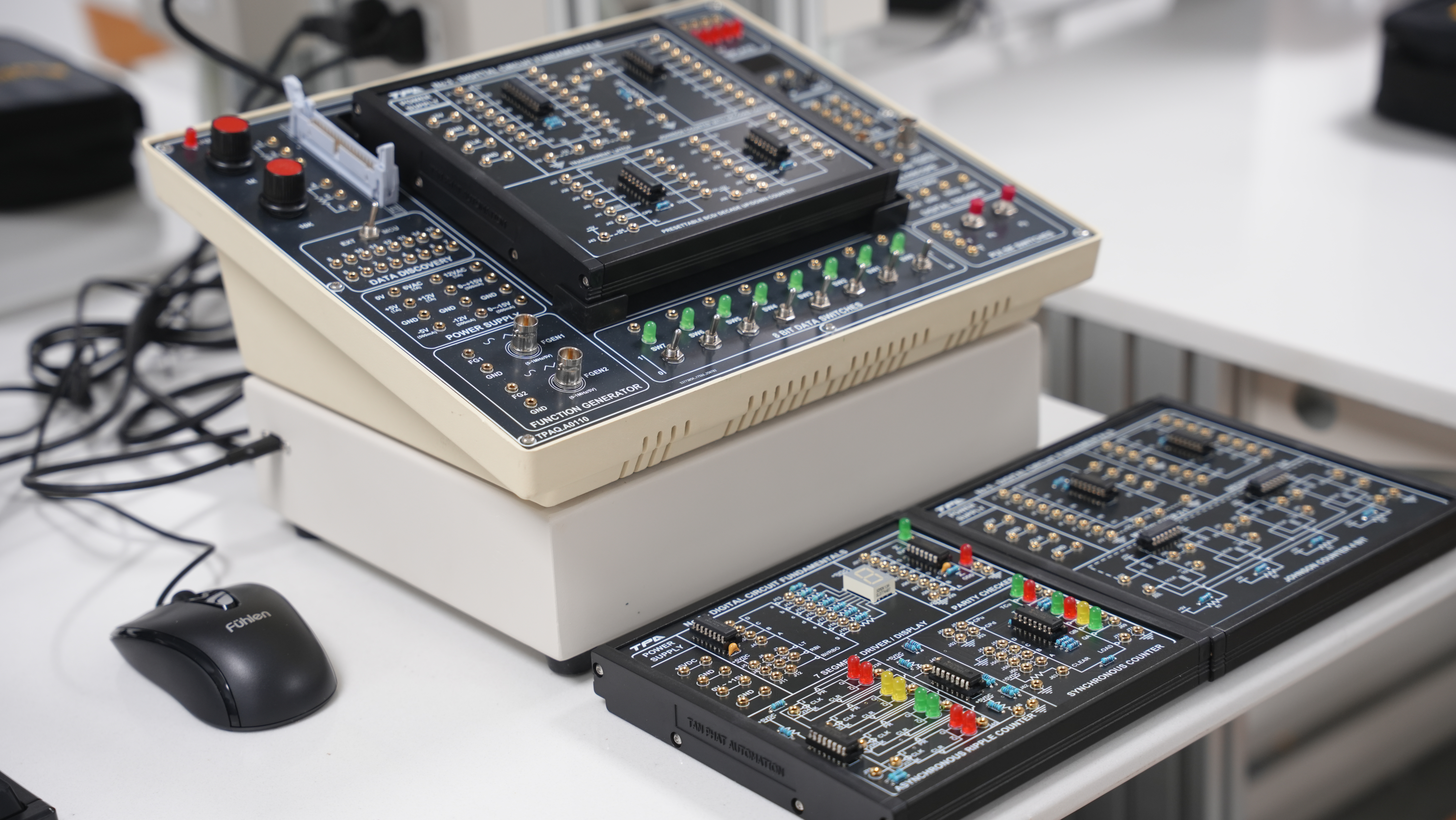
  • 01 basic electronics training kit
  • Standard accessories:
  • M2 connectors
  • Power cables
  • User manual
  • Standard accessories:
  • Power cables
  • User instruction manual

Specialized Software for Basic Electronics Practice

General Introduction:

  • The software is developed on the LabVIEW platform.
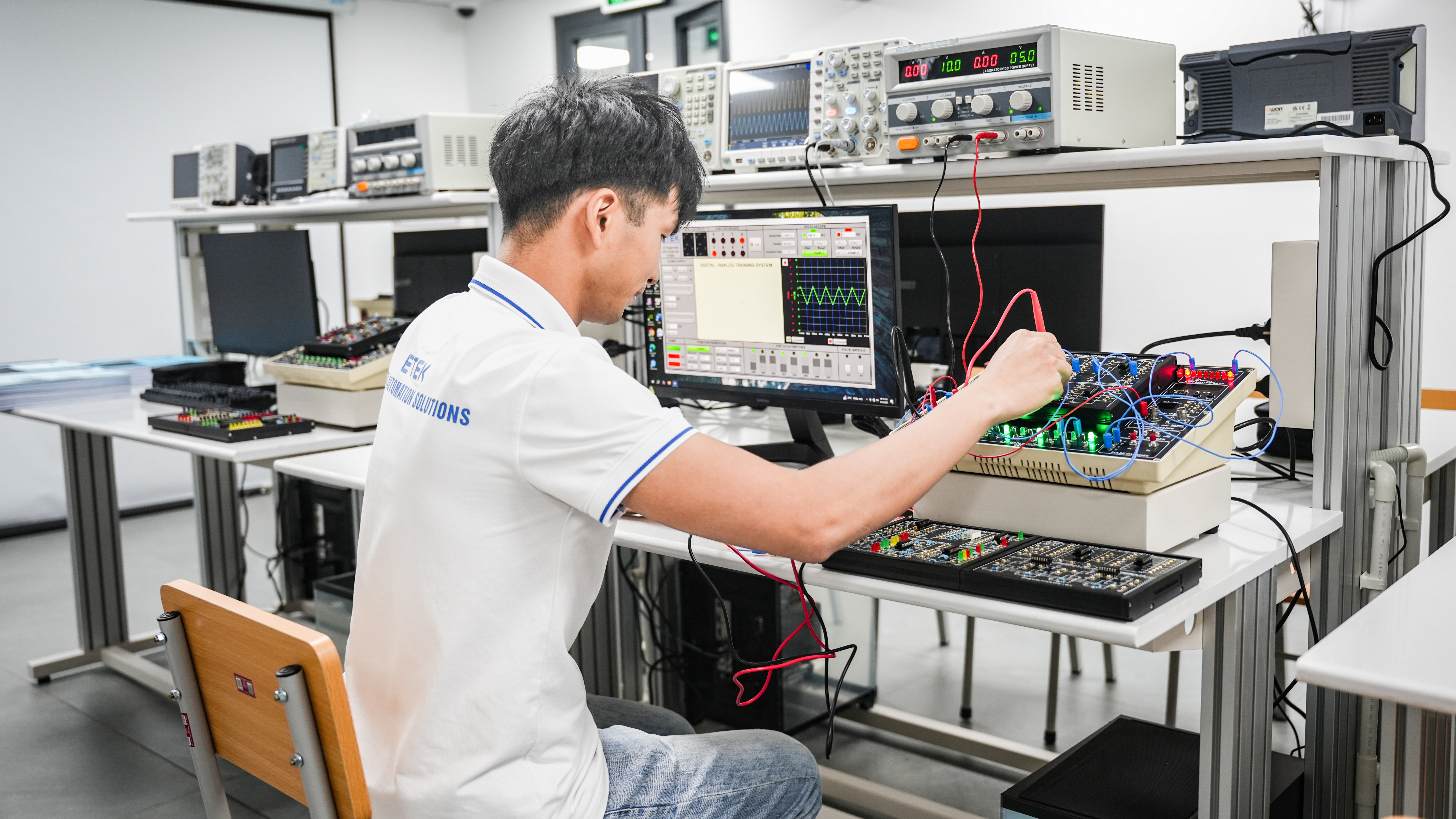
  • The software is designed to work in conjunction with the main basic electronics training kit and functional training modules, thereby simulating the operation of functional kits.
  • The software allows adjustment of output power supply parameters delivered to the module, such as voltage, frequency, etc.
  • The software measures and displays values collected at measurement points of functional modules, such as voltage, current, frequency, waveform, etc.
  • Capable of connecting and interacting with hardware.
  • User-friendly and intuitive graphical interface.

Software Functions:

DC Power Supply Interface:

  • Adjust positive voltage via software interface
  • Adjust negative voltage via software interface
  • Display adjusted voltage values on the software interface

Function Generator Interface:

  • Dual-channel pulse generation
  • Supports simultaneous or independent signal output
  • Selectable output waveforms: sine wave, square wave, triangle wave
  • Adjustable frequency and amplitude
  • Adjustable duty cycle for square and triangle waves

Oscilloscope Interface:

  • Displays measured waveforms on the software interface
  • Two independent measurement channels, selectable or simultaneous display
  • Adjustable V/div and offset for each channel
  • Adjustable Time/div settings

DC Voltage Meter Interface:

  • Displays voltage values on the interface

Digital Data Display Interface:

  • Simulates display using single LEDs
  • Simulates display using 7-segment LED
  • Connects and interacts with training modules for data acquisition
  • Simulates interaction between the main basic electronics system and modular training units
  • Allows selection of display devices
  • Box dimensions: 330 x 264 x 109 (W x D x H)
  • Designed and manufactured under processes compliant with the following systems/standards:
  • ISO 9001:2015 – Quality Management System
  • ISO 14001:2015 – Environmental Management System
  • ISO 45001:2018 – Occupational Health and Safety Management System
  • ISO/IEC 27001:2022 – Information Security Management System
  • ISO 50001:2018 – Energy Management System
  • Module input power supply: 220 VAC / 50 Hz

DC Output Power Unit:

  • Adjustable power supply: adjustable via potentiometer or software interface
  • Fixed outputs: ±5V / 500mA, ±12V / 500mA

Function Generator Unit:

  • Frequency range: 0 – 1 MHz
  • Frequency adjustment via rotary knob or software interface
  • Selectable waveform output: sine, square, and triangle wave
  • TTL level output: 0 – +5 V

Oscilloscope Signal Measurement Unit:

+ 02-channel oscilloscope (1MΩ, 14-bit, 100 MS/s)

  • Spectrum and waveform analysis when connected to a computer
  • Output can also be connected to an external oscilloscope

AC Output Power Unit:

  • Fixed AC output: 12V / 1A / 50Hz
  • Fixed AC output: 6V / 1A / 50Hz

8-Bit Data Switch Unit:

+ 8 logic switches; position “1” outputs high signal, position “0” outputs low signal

Potentiometer Unit:

  • VR1 = 1K potentiometer
  • VR2 = 10K potentiometer

7-Segment Display Unit:

  • 2-digit 7-segment display
  • 2 BCD input channels

8-Bit LED Display Unit:

+ 8 LED input channels

  • LEDs light up at HIGH level and turn off at LOW level

LCD Display Unit:

  • Displays measured values such as voltage, frequency, etc.
  • Computer connection port: USB
  • Equipped with expansion slots for additional experimental modules
PRODUCT LIST