Home » Hydraulic pneumatic » PNEUMATIC SERVO CONTROL CIRCUIT TRAINING PANEL
PNEUMATIC SERVO CONTROL CIRCUIT TRAINING PANEL
Product Code:
Price: Contact
- Device information
- Specifications
General Specifications
- Power supply: single-phase AC 220 VAC, 50 Hz
- Material of equipment mounting table: T-slotted aluminum
- Integrated with various types of sensors
- Electrical and hydraulic mechanisms: solenoid valve, hydraulic proportional valve, position sensor
- Operating modes: position control, speed control
- Designed and manufactured under processes compliant with the following systems/standards:
- ISO 9001:2015 – Quality Management System
- ISO 14001:2015 – Environmental Management System
- ISO 45001:2018 – Occupational Health and Safety Management System
- ISO/IEC 27001:2022 – Information Security Management System
- ISO 50001:2018 – Energy Management System
- Mounting base for pneumatic components:
. Aluminum alloy, with scratch-resistant surface treatment
. Self-locking ABS plastic feet with cylindrical tips slotted in a “+” shape to provide elasticity
- Method of mounting equipment onto the training table:
. Uses a self-locking plastic foot structure, allowing users to quickly and conveniently install and remove components on the aluminum tabletop
. The cylindrical tips of the plastic feet are compressed by the aluminum slots on the tabletop, reducing their cross-section to enter the table slots. After entering the slots, the plastic feet elastically return to their original shape, forming a locking latch that firmly secures the pneumatic components to the tabletop.
- Electrical control modules
- Mounting base material: Aluminum alloy, with black scratch-resistant surface treatment.
- Mounting method: Self-retaining mechanism for securing the module assembly onto the training panel, convenient for installation and removal.
- Module surface: Scratch-resistant and anti-glare electronic circuit surface, suitable for teaching and training.
- Plastic end caps at both ends of the module: One-piece molded plastic.
+ 2 mm quick-connect sockets for convenient wiring
Training Contents
- Adjust and observe parameter values of the pneumatic servo unit
- Build a PID model for pneumatic position and speed control
- Adjust PID controller parameters
- Electrically connected control and mechanical structure
- Apply sensors and pneumatic components in an automated system
- Applications on the control panel
- Connection / setup applications
- Diagnosis, detection, and repair
Acquired Skills
- Basic skills in operating principles and calculation methods for pneumatic drive systems and pneumatic control systems, as well as the ability to build system control circuits
- Thinking skills, design objectives, design thinking, and analysis
- Skills in identifying failure causes and solving problems occurring in pneumatic circuits
Equipment List
- 01 pneumatic cylinder position and speed control experiment unit using servo valve
- 01 pneumatic proportional pressure regulator
- 01 pneumatic servo control valve
- 01 filter-regulator unit
- 01 air distribution unit
- 02 pressure sensors
- 01 DC power supply module
- 01 data acquisition module
- 01 vacuum generator
- 01 normally closed 3/2-way pneumatic solenoid valve
- 01 5/2-way pneumatic solenoid valve, single coil
- 01 5-pin M8 female connection cable
- 01 industrial computer
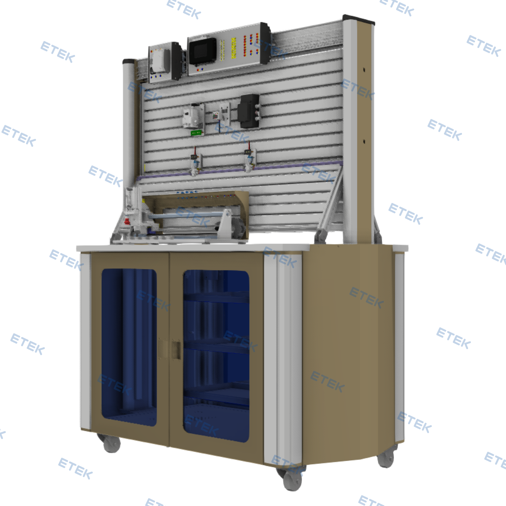
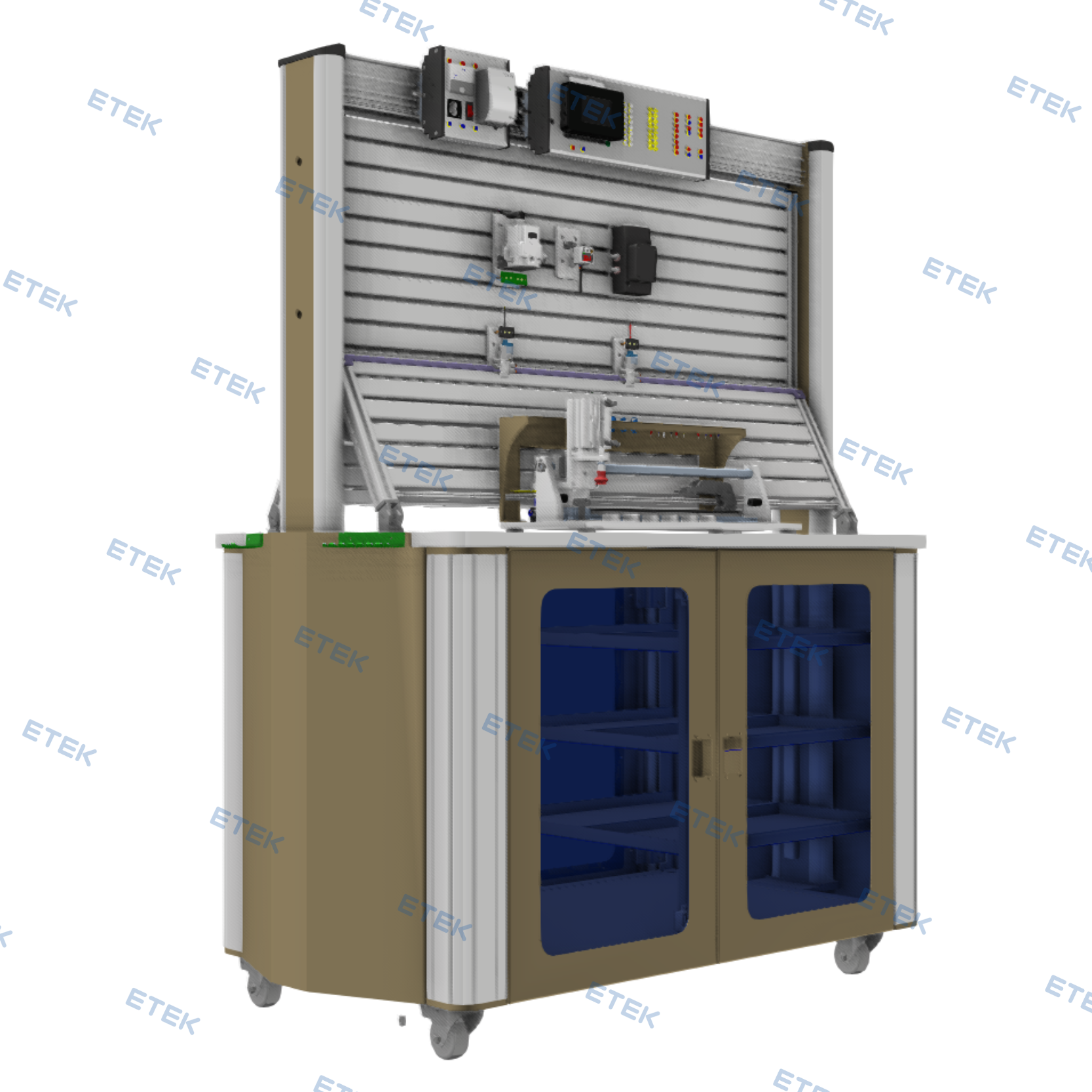
- 01 dedicated training table for pneumatic and electro-pneumatic training
- 01 air compressor with storage tank
1. Pneumatic Cylinder Position and Speed Control Experiment Unit Using Servo Valve – TPAK.B4000
- 01 pneumatic rodless cylinder, stroke 400 mm
- 01 length measuring sensor, 400 mm, output 0 – 10 VDC
- Graduated measuring scale
- Vacuum suction cup unit
2. Pneumatic Proportional Pressure Regulator – TPAK.G6000
- Minimum supply pressure: set pressure + 0.1 MPa
- Maximum supply pressure: 1.0 MPa
- Output pressure range: 0.005 to 0.5 MPa
- Input signal: 4 to 20 mA DC or 0 to 10 V DC
- Output signal:
- Analog signal: 4 to 20 mA DC or 0 to 5 V DC
- Digital signal: PNP or NPN
- Power supply: 24 V DC ±10%
- Linearity: ±1% full scale
- Hysteresis: ≤ 0.5% full scale
3. Pneumatic Servo Control Valve – TPAK.G7000
- Operating pressure: +0…10 bar, 0…150 psi
- Power requirement: 12 ± 2 VDC or 24 ± 4 VDC @ 20 W
- Command input impedance: 0…10 VDC: 100 kΩ; 4…20 mA: 210 Ω
- Feedback input impedance: 0…10 VDC: 100 kΩ; 4…20 mA: 210 Ω
- Command input: configurable 0…10 VDC; 4…20 mA
- Feedback input: configurable 0…10 VDC; 4…20 mA
- Electronic adjustment: user interface connectable via USB
- Status indicators: 2 LEDs for power and status
- Excitation: +10 V, max. 15 mA
4. Filter-Regulator Unit – TPAK.C2000
Technical Specifications
- The integrated device includes: 01 filter-regulator unit and 01 3/2-way shut-off valve
- The 3/2-way distribution valve is used to shut off and supply compressed air to all pneumatic components. Its function is similar to an “air supply power switch”.
- The 3/2-way distribution valve can be locked with a key to prevent students from opening it when there is no practical training session.
- Filtration rating: up to 5 micrometers
- Pressure adjustment range: 0.5 – 7 bar
- Quick connector size, inlet/outlet: Ø6 mm
Main Components:
- 01 aluminum base
- 01 3/2-way shut-off valve
- 04 plastic feet
- 01 filter-regulator unit
5. Air Distribution Unit – TPAK.C6000
Technical Specifications
- Number of ports: 09 ports
- Port size: 4 mm quick connector
- Inlet: Ø6 mm
- The air supply ports are one-way valve type. When no pneumatic tube is inserted, the valve automatically closes to prevent air leakage.
Main Components
- 01 aluminum base
- 01 air manifold
- 04 plastic feet
- 09 self-locking quick connectors
6. Pressure Sensor – TPAK.F4100
- Power supply: 12 to 24 VDC
- Current consumption: 50 mA
- Operating pressure range: 0 – 1000 kPa
- PNP output
- Maximum PNP output current: 100 mA
- 4-digit, 7-segment LED display
- Display pressure range: -50 to 1100 kPa
- Quick connector size: Rc 1/8
- Equipment mounting base: aluminum alloy, with scratch-resistant surface treatment
7. DC Power Supply Module – TPAK.A7300
Technical Specifications
- Compliant with TCVN 5699-1:2010 and IEC 60335-1:2010 standards for power consumption and current, leakage current, and electric strength
- Input voltage: 100 – 240 VAC
- Output voltage: 24 VDC / 4.2 A
- Power: 100 W
- Short-circuit protection and LED indicator
8. Data Acquisition Module – TPAK.B5000
- Xilinx processor
- Number of analog inputs: 6 AI
- Number of analog outputs: 4 AO
- Number of digital outputs: 16 DIO
- USB connection port
- Module designed as an aluminum box with one-piece molded plastic end caps at both ends
- Connection terminals are brought out to M2 quick plug terminals
9. Vacuum Generator – TPAK.R0100
Technical Specifications
- Vacuum generator valve
- Working pressure range: 0.1 to 0.6 MPa
- Minimum vacuum pressure: -88 kPa
- Suction tube diameter: 1 mm
- Maximum flow rate: 24 L/min
- Air consumption: 46 L/min
- Connection port size: 1/8″
Main Components:
- 01 aluminum base
- 04 plastic feet:
- 03 quick connectors
- 01 vacuum generator valve
- 01 vacuum suction cup
10. Normally Closed 3/2-Way Pneumatic Solenoid Valve – TPAK.K0100
Technical Specifications
- Working pressure range: 0.15 to 0.7 MPa
- Response time: 25 ms or less, at 0.5 MPa pressure
- Normally closed valve type, NC
- Quick connection port: M5
- Spring return
- LED operation indicator with protection circuit
- Coil voltage: 24 VDC
Main Components:
- 01 aluminum base
- 04 plastic feet
- 01 silencer
- 01 3/2-way NC solenoid valve
- 02 quick connectors
- 01 circuit board
11. 5/2-Way Pneumatic Solenoid Valve, Single Coil – TPAK.L0100
Technical Specifications
- Working pressure range: 0.15 to 0.7 MPa
- Response time: 15 ms or less
- Normally closed valve type, NC
- 4 mm quick connector
- Spring return and manual actuation
- LED operation indicator with protection circuit
- Coil voltage: 24 VDC
Main Components:
- 01 aluminum base
- 04 plastic feet:
- 02 silencers
- 01 5/2-way single-coil valve
- 01 quick connector
- 01 circuit board
12. 5-Pin M8 Female Connection Cable – M8B-M05-C
13. Industrial Computer
14. Dedicated Training Table for Pneumatic and Electro-Pneumatic Training – TPAB.M2110
Technical Specifications
- Overall dimensions: 1280 x 766 x 1600 mm, L x W x H
- The table consists of 2 main sections: mobile practice table and pneumatic mounting panel
- Mobile practice table
- Overall dimensions: 1280 x 766 x 860 mm, L x W x H
- Material: CT3 powder-coated steel combined with aluminum profiles
+ 4 corners made of molded aluminum profiles, dimensions 710 x 92 x 92 mm, R42 mm rounded corners, and 11 holes with a diameter of 6.8 mm
- Divided into 2 compartments: compartment 1 includes 04 equipment storage drawers; compartment 2 is a large compartment for storing larger devices
+ 04 CT3 powder-coated steel doors, dimensions 728 x 463 x 42 mm, with transparent mica panels, dimensions 638 x 372 x 3 mm, for observing the equipment inside
- Cabinet side panels made of CT3 powder-coated steel, dimensions 755 x 547 x 120 mm, with 160-degree folded edges and 06 slotted mounting holes
- Table legs equipped with casters and locking brakes.
- LED lighting inside the cabinet for convenient item searching
- Tabletop:
. Dimensions: 1140 x 766 x 25 mm, L x W x H
. Material: engineered wood with scratch-resistant and insulating coating.
- Test lead holder
. Includes 02 cable hanging racks.
. Material: stainless steel, 2 mm thick, with scratch-resistant surface.
. Capacity: up to 40 leads
- Pneumatic mounting panel support frame
. Support frame made of aluminum combined with CT3 powder-coated steel
. 02 aluminum bars with R25 mm rounded profile, length 1500 mm
. 01 CT3 steel bar, dimensions 1499 x 46.5 x 100 mm
- Vertical mounting rack for pneumatic devices:
. Dimensions: 1133 x 30 x 406 mm, L x W x H.
. Mounting rack material: assembled from 03 aluminum profile bars, dimensions 1073 x 137 x 24.5 mm, anodized for scratch resistance and aesthetics, with specialized assembly structure.
. Both sides of the aluminum bar include 3 slots, each 8.2 mm wide and 21.7 mm deep, spaced 44.4 mm apart
. Practical training devices can be mounted from both sides.
- Inclined mounting rack for pneumatic devices:
. 02 symmetrical racks
. Inclination angle: 60 degrees relative to the tabletop
. Dimensions: 1133 x 30 x 297 mm, L x W x H.
. Mounting rack material: assembled from 02 aluminum profile bars, dimensions 1073 x 137 x 24.5 mm, anodized for scratch resistance and aesthetics, with specialized assembly structure.
. Both sides of the aluminum bar include 3 slots, each 8.2 mm wide and 21.7 mm deep, spaced 44.4 mm apart
- Mounting rack for electrical devices:
. Dimensions: 1144 x 92 x 80.5 mm
. Mounting rack material: 2 mm thick anodized aluminum profile, ensuring scratch resistance and aesthetics, with specialized assembly structure.
. Aluminum plate dimensions: 86 x 13.4 x 1136 mm, with module mounting positions spaced at 18 mm, 12 mm, 24.5 mm, and 26.5 mm
. Includes 2 aluminum bars, allowing practical training devices to be mounted from both sides.
Main Components:
- 01 tabletop
- 01 mobile practice table
- 01 vertical mounting rack for pneumatic devices:
- 02 inclined mounting racks for pneumatic devices:
- 01 mounting rack for electrical devices:
- 02 test lead holders
15. Air Compressor with Storage Tank – TPAK.C0101
- Dedicated laboratory air compressor with very low noise level
Technical Specifications
- Dimensions: 600 x 300 x 600 mm, L x W x H
- Dedicated laboratory air compressor with very low noise level
- Operating voltage: 220 VAC, 50 Hz
- Power: 550 W
- Noise level: 65 dB
- Tank capacity: 30 L
Main Components:
- 01 silent air compressor
- 01 quick connector
- 01 air hose
16. ETEK-Lab Digitalization and Practice Support Software
a. General Features
- Vietnamese-language interface, user-friendly and easy to use.
- Web-based operation, accessible through an Internet browser.
- Allows access anytime and anywhere using a personal account.
- Supports login with individual usernames and passwords for each user.
- Supports role-based access control for different user groups, including teachers and students.
- Supports storage and use of lecture content, learning materials, and practical training documents.
- Course content, lectures, and practical exercises can be continuously updated by users.
- Supports effective use of theoretical materials and practical content associated with training equipment.
- Software data is deployed on the supplier’s Cloud Server.
- The software has a Copyright Registration Certificate issued by the Copyright Office.
b. Lecture Development Support Functions
- Import lecture content from Word files.
- Create and edit lectures directly on the software.
- Support insertion of visual illustrative images.
- Support multiple types of multiple-choice questions.
- Allow development of a question bank for testing and assessment.
- Manage lecture content.
c. Integration of AI Technology to Support Teaching
- The software integrates artificial intelligence, AI, technology to support teachers in developing training content, preparing lectures, and designing tests.
- AI helps reduce lesson preparation time and supports fast, systematic, and effective development of training content.
- Supports the development of lecture structures based on topics or subject content.
- Automatically generates key lecture components, including learning objectives, knowledge content, illustrative examples, and discussion questions.
- Supports summarizing long documents into key teaching content.
- Supports converting technical documents into lecture content that is easier for students to understand.
- Supports editing and improving lectures, as well as adding illustrative examples or real-world scenarios.
- Generates illustrative images and visual diagrams suitable for lesson content.
- Automatically generates test questions from lecture content, including multiple-choice, true/false, matching, and fill-in-the-blank questions.
d. Simulation
- Simulation of actuator operation: screw motor
- Simulation of actuator operation: gear motor
- Simulation of actuator operation: turbine motor
- Simulation of actuator operation: vane motor
- Simulation of distribution device operation: air manifold
- Simulation of distribution device operation: air tank
- Simulation of valve operation: 3/2-way valve controlled by a sensing probe
- Simulation of valve operation: 3/2-way valve controlled by a foot pedal
- Simulation of valve operation: 3/2-way valve controlled by a limit switch
- Simulation of valve operation: 3/2-way valve controlled by pneumatic actuation, direct control and assisted-valve control
- Simulation of valve operation: 3/2-way valve controlled by electro-pneumatic actuation, direct control and assisted-valve control
- Simulation of valve operation: 4/2-way valve controlled by a switch
- Simulation of valve operation: 4/2-way valve controlled by a sensing probe
- Simulation of valve operation: 4/2-way valve controlled by single-sided pneumatic actuation
- Simulation of valve operation: 4/2-way valve controlled by single-sided electro-pneumatic actuation
- Simulation of valve operation: 5/2-way valve controlled by single-sided pneumatic actuation
- Simulation of valve operation: 5/2-way valve controlled by single-sided electro-pneumatic actuation
- Simulation of valve operation: 5/3-way valve controlled by double-sided pneumatic actuation
- Simulation of valve operation: 5/3-way valve controlled by double-sided electro-pneumatic actuation
- Simulation of valve operation: OR logic valve
- Simulation of valve operation: AND logic valve
- Simulation of valve operation: one-way valve, non-adjustable and adjustable types
- Simulation of valve operation: quick exhaust valve
- Simulation of valve operation: vacuum valve
- Simulation of valve operation: slow-closing time control valve
- Simulation of valve operation: slow-opening time control valve
- Simulation of pneumatic control circuit operation: manual control, direct and indirect
- Simulation of pneumatic control circuit operation: time-based control, semi-automatic and automatic
- Simulation of pneumatic control circuit operation: stroke-based control, automatic
- Simulation of pneumatic control circuit operation: sequence-based control, automatic
- Simulation of electro-pneumatic control circuit operation: manual control, direct and indirect
- Simulation of electro-pneumatic control circuit operation: time-based control, semi-automatic and automatic
- Simulation of electro-pneumatic control circuit operation: stroke-based control, automatic
- Simulation of electro-pneumatic control circuit operation: cascade control, automatic
- Simulation of electro-pneumatic control circuit operation: sequence-based control, automatic
- Simulation of electro-pneumatic machine control circuit operation: circuit assembly and operation of a workpiece feeding station, non-automatic and automatic
- Simulation of electro-pneumatic machine control circuit operation: circuit assembly and operation of a drilling station, non-automatic and automatic